SPI Peripheral Design in SystemVerilog
2025-10-15 | By Mustahsin Zarif
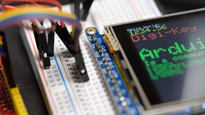
Serial Peripheral Interface (SPI for short) is a common synchronous, serial, and full-duplex communication protocol used in electronics. If you have ever used sensors/actuators (e.g., SPI TFT Displays) that had the pins MOSI, MISO, CS, and CLK, then you have already used SPI for your embedded systems project. SPI needs these 4 pins to work, and they stand for:
MISO: Master In, Slave Out → data leaving from the controller to the peripheral
MOSI: Master Out, Slave In → data leaving from the peripheral to the controller
CS: Chip Select → the peripheral to communicate with
CLK: Clock → for synchronous data transmission
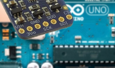
You also need to power the chip/peripheral you are using, so you probably remember seeing VDD and GND pins on chips as well. What is more, while each peripheral comes with only one CS pin, the controller can have multiple CS pins. Depending on which peripheral you want to communicate with, the respective CS line is pulled low. I have used SPI before to display images and GIFs on a SPI TFT display using an Arduino, but you can’t really tell how the protocol works under the hood when you use all the readily available libraries and example code on the internet. Therefore, a fun and rewarding way to test my knowledge of SPI came from implementing the protocol in SystemVerilog and running it with Quartus and Modelsim. Let’s look at the peripheral design in this blog and leave the controller for a future series.
Here is an I/O relational diagram to represent SPI:

Now I want you to notice a few design considerations for my tested module. First of all, the [1:0] MODE is because SPI actually has 4 different modes it can work in. We will only test for MODE 0. Secondly, my design only works for 8-bit transfers, but in practice, multiple bytes of data can be exchanged as long as CS is held low.
With these two considerations out of the way, let’s do a brief recap on how the I/O of the peripheral works!
Inputs
RST: reset
CLK: system clock (e.g., if your FPGA has a 125 MHz clock)
SCLK: clock generated by the master to operate at a target frequency much lower than the FPGA clock frequency
MOSI: bit coming from controller
CS: if held at logic 0, it means the controller wants to communicate with the peripheral
Outputs
DONE: signal that a whole byte has been received by the peripheral and sent to the controller
MISO: bit going to controller
[7:0] RECEIVED_DATA: register to hold the byte that came from the controller, so that we can do verification
That’s it! We can start writing our spi_slave module in SystemVerilog.
(I should mention that Controller == Master and Peripheral == Slave. Controller and Peripheral are used nowadays instead for reference, but devices still come with the original labels. I’ll stick to the new terminology.)
Opening up VS Code and having the SystemVerilog extension installed, I quickly write up my module and port declarations:
module spi_slave (

    input logic clk, 			// logic allows sv to infer what logic type to use, e.g. wire or reg

    input logic rst,

    input logic sclk,

    input logic cs,

    input logic mosi,

    output logic miso, 			//bit by bit data out of the slave

    output logic done,

    output logic [7:0] received_data 	//8-bit value produced by the slave and exposed outward

);
Followed by my internal logic declaration:
logic sclk_delayed;			//delay sclk by one clock cycle to check transition rise, fall, or steady

    logic sclk_rising; 			//rising edge of sclk

    logic sclk_falling; 			//falling edge of sclk


    logic [7:0] shift_reg_in;

    logic [7:0] shift_reg_out; 		//8-bit shift register to hold the received data

    logic [2:0] bit_count; 		//3-bit counter to keep track of the number of bits received
I can drive my sclk_rising and sclk_falling signals using assign statements:
assign sclk_rising = (sclk && !sclk_delayed);            //detect rising edge of sclk (1 after 0). At all times,						                                                             //evaluate this condition and set sclk_rising accordingly.

    assign sclk_falling = (!sclk && sclk_delayed); 	    //detect falling edge of sclk (0 after 1)
sclk_delayed is assigned using non-blocking assignment statement in a flip-flop:
Code snippet → sclk_delayed <= sclk; //delay sclk by one clock cycle
Now we can write logic for our Finite State Machine. Here is a pictorial diagram of what we want to design:

This is a Moore model (output depends on state only, i.e., done = 1 if state == DONE). What the diagram shows is that the peripheral sits idly until CS is pulled low. Once in the receiving state, it stays there until all 8 bits have been read from the controller (bit_count goes from 0 to 7). After the 8th bits of both peripheral and controller have been transmitted, we wait for SCLK to rise, and we signal completeness.
After coding the entire spi_salve module design, we can import it into Intel Quartus Prime and view the state machine and RTL (Register-Transfer Level):


FSM: Check ✅

RTL is massive 😵💫 let’s trust it’s correct for now and simulate our design in Modelsim.
I wrote a simple testbench in SystemVerilog to test if the design works. After running it in Modelsim to view the waveform of signals, the result looks promising!
.do file to run simulation:
# spi_slave_wave.do

# Compile the design and testbench

vlog ../rtl/spi_slave.sv

vlog ../tb/spi_slave_tb.sv

# Simulate the testbench

vsim spi_slave_tb

# Add all signals to the waveform

add wave -position insertpoint sim:/spi_slave_tb/*

# Run the simulation long enough to capture all activity

run 1000ns

# Zoom to fit waveform

wave zoom full
Test byte in testbench file sent to peripheral in simulation:
 // Send byte 0x3C
spi_send_byte(8'h3C);

✅received_data gets 00111100 in binary or 3C in hexadecimal when done = 1
✅sclk frequency < clk frequency
✅CS is low during transactions
Great! We have finished designing our very own SPI peripheral module in SystemVerilog that supports single-byte communication in SPI mode 0. We introduced SPI overall, briefly using an I/O diagram to know what we are trying to build. We followed this by focusing only on the ports for the Peripheral module and the internal logic signals required for functionality. We saw the logical flow of the system from IDLE → RECEIVING → DONE → IDLE using a drawing, and saw this reflected once the design was synthesized in Quartus Prime Lite. Finally, we used Modelsim to simulate our design and view the generated waveform to verify correctness. All the code can be found on my GitHub with a README at https://github.com/mmzarif/spi_project. The peripheral design was actually the easy part, since, for example, the FSM had only 3 states and we did not have to generate SCLK on this side. Next time, we will go over the controller module design process!