Fundamentals: Understand the Characteristics of Capacitor Types to Use Them Appropriately and Safely
Contributed By DigiKey's North American Editors
2020-09-17
Capacitors are energy storage devices that are essential to both analog and digital electronic circuits. They are used in timing, for waveform creation and shaping, blocking direct current, and coupling of alternating current signals, filtering and smoothing, and of course, energy storage. Due to the wide range of uses, an abundance of capacitor types has emerged using a variety of plate materials, insulating dielectrics, and physical forms. Each of these capacitor types are intended for a specific range of applications. The wide variety of options means it can take time to sort through them all to find the optimum choice for a design in terms of performance characteristics, reliability, lifespan, stability, and cost.
A knowledge of the characteristics of each capacitor type is required in order to properly match the capacitor to the intended circuit application. This knowledge must cover the electrical, physical, and economic characteristics of capacitors.
This article will describe the various types of capacitors, their characteristics, and the key criteria for their selection. Examples from Murata Electronics, KEMET, Cornell Dubilier Electronics, Panasonic Electronics Corporation, and AVX Corporation will be used to illustrate key differences and attributes.
What is a capacitor?
The capacitor is an electronic device that stores energy in an internal electric field. It is a basic passive electronic component along with resistors and inductors. All capacitors consist of the same basic structure, two conducting plates separated by an insulator, called the dielectric, that can be polarized with the application of an electric field (Figure 1). Capacitance is proportional to the plate area, A, and inversely proportional to the distance between the plates, d.
 Figure 1: The basic capacitor consists of two conducting plates separated by a non-conducting dielectric which stores energy as polarized regions in the electric field between the two plates. (Image source: DigiKey)
The first capacitor was the Leyden jar, developed in 1745. It comprised a glass jar lined with metal foil on the inner and outer surfaces and was originally used to stored static electric charges. Benjamin Franklin used one to prove that lightning was electricity, which became one of the earliest recorded applications.
The capacitance of the basic parallel plate capacitor can be calculated using Equation 1:
 Equation 1
Where:
C is the capacitance in Farads
A is the plate area in square meters
d is the distance between the plates in meters
ε is the permittivity of the dielectric material
ε is equal to the relative permittivity of the dielectric, εr, multiplied by the permittivity of a vacuum, ε0. The relative permittivity, εr, is often referred to as the dielectric constant, k.
Based on Equation 1, capacitance is directly proportional to the dielectric constant and plate area, and inversely proportional to the distance between the plates. To increase capacitance, the area of the plates can be increased and the distance between the plates can be decreased. Since the relative permittivity of a vacuum is 1, and all dielectrics have a relative permittivity greater than 1, inserting a dielectric will also increase the capacitance of a capacitor. Capacitors are generally referred to by the type of dielectric material used (Table 1).
 Table 1: Characteristics of common capacitor types, sorted by dielectric material. (Table source: DigiKey)
Some notes on the column entries:
- The relative permittivity or dielectric constant of a capacitor affects the maximum value of capacitance achievable for a given plate area and dielectric thickness.
- The dielectric strength is a rating of the dielectric’s resistance to voltage breakdown as a function of its thickness.
- The minimum achievable dielectric thickness affects the maximum capacitance that can be realized, as well as the capacitor’s breakdown voltage.
Capacitor construction
Capacitors are available in a variety of physical mounting configurations, including axial, radial, and surface mount (Figure 2).
 Figure 2: Capacitor mounting, or configuration types include axial, radial, and surface mount. Surface mount is very widely used at this time. (Image source: DigiKey)
The axial construction is based on alternate layers of metal foil and dielectric, or a dielectric metalized on both sides rolled into a cylindrical shape. Connections to the conducting plates can be via an inserted tab or a circular conducting end cap.
The radial type usually consists of alternating metal and dielectric layers. Metal layers are bridged at the ends. Radial and axial configurations are intended for through-hole mounting.
Surface mount capacitors also rely on alternate conducting and dielectric layers. The metal layers at each end are bridged by a solder cap for surface mounting.
Capacitor circuit model
The circuit model for a capacitor includes all three passive circuit elements (Figure 3).
 Figure 3: The circuit model for a capacitor consists of the capacitive, inductive, and resistive elements. (Image source: DigiKey)
The circuit model of a capacitor consists of a series resistive element representing the ohmic resistance of the conducting elements along with the dielectric resistance. This is called the equivalent, or effective, series resistance (ESR).
The dielectric effects occur when AC signals are applied to the capacitor. AC voltages cause the polarization of the dielectric to change on every cycle, causing internal heating. The dielectric heating is a function of the material and is measured as the dissipation factor of the dielectric. The dissipation factor (DF) is a function of the capacitor’s capacitance and ESR, and can be calculated using Equation 2:
 Equation 2
Where:
XC is the capacitive reactance in ohms (Ω)
ESR is the equivalent series resistance (in Ω)
The dissipation factor is frequency dependent due to the capacitive reactance term and is dimensionless, often expressed as a percentage. A lower dissipation factor results in less heating and therefore lower loss.
There is a series inductive element, called the effective or equivalent series inductance (ESL). This represents lead and conductive path inductance. The series inductance and capacitance give rise to a series resonance. Below the series resonant frequency, the device exhibits primarily capacitive behavior, above it, the device is more inductive. This series inductance can be problematic in many high-frequency applications. Suppliers minimize inductance by using the layered construction shown in the radial and surface mount component configurations.
The parallel resistance represents the insulation resistance of the dielectric. The values of the various model components are dependent upon the capacitor configuration and the materials selected for its construction.
Ceramic capacitors
These capacitors use a ceramic dielectric. There are two classes of ceramic capacitors, Class 1 and Class 2. Class 1 is based on para-electric ceramics like titanium dioxide. Ceramic capacitors in this class have a high level of stability, good temperature coefficient of capacitance, and low loss. Due to their inherent accuracy, they are used in oscillators, filters, and other RF applications.
Class 2 ceramic capacitors use a ceramic dielectric based on ferro-electric materials like barium titanate. Due to the high dielectric constant of these materials, the Class 2 ceramic capacitors offer a higher capacitance per unit volume but have lower accuracy and stability than Class 1 capacitors. They are used for bypass and coupling applications where the absolute value of capacitance is not critical.
Murata Electronics’ GCM1885C2A101JA16 is an example of a ceramic capacitor (Figure 4). The Class 1 100 picoFarad (pF) capacitor has 5% tolerance, is rated at 100 volts, and comes in a surface mount configuration. This capacitor is intended for automotive use with a temperature rating of -55° to +125° C.
 Figure 4: The GCM1885C2A101JA16 is a Class 1, 100 pF ceramic surface mount capacitor with 5% tolerance and a rating of 100 volts. (Image source: Murata Electronics)
Film capacitors
Film capacitors use a thin plastic film as a dielectric. Conducting plates can be implemented either as foil layers or as two thin layers of metallization, one on each side of the plastic film. The plastic used for the dielectric determines the characteristics of the capacitors. Film capacitors come in many forms:
Polypropylene (PP): These have particularly good tolerance and stability with low ESR and ESL and high voltage breakdown ratings. Due to temperature limits of the dielectric they are available only as leaded devices. The PP capacitors find applications in circuits where high power or high voltage are encountered like switch mode power supplies, ballast circuits, high frequency discharge circuits, and in audio systems where their low ESR and ESL are prized for signal integrity purposes.
Polyethylene terephthalate (PET): Also called polyester or mylar capacitors, these capacitors are the most volumetrically efficient of the film capacitors due to their higher dielectric constant. They are generally applied as radial lead devices. They are used for general purpose capacitive applications.
Polyphenylene sulfide (PPS): These capacitors are manufactured only as metallized film devices. They have particularly good temperature stability and so are applied in circuits that require good frequency stability.
An example PPS film capacitor is the ECH-U1H101JX5 from Panasonic Electronics Corporation. The 100 pF device has a tolerance of 5%, is rated at 50 volts, and comes in a surface mount configuration. It has an operating temperature range of -55° to 125°C and is intended for general electronics applications.
Polyethylene naphthalate (PEN): Like the PPS capacitors, these are only available in a metalized film design. They have high temperature tolerance and are available in surface mount configuration. Applications focus on those requiring high temperature and high voltage performance.
Polytetrafluoroethylene (PTFE) or Teflon capacitors are noted for their high temperature and high voltage tolerance. They are manufactured in both metalized and foil construction. PTFE capacitors mostly find applications requiring exposure to high temperature.
Electrolytic capacitors
Electrolytic capacitors are notable for their high capacitance values and high volumetric efficiency. This is achieved by using a liquid electrolyte as one of its plates. An aluminum electrolytic capacitor comprises four separate layers: an aluminum foil cathode; an electrolyte-soaked paper separator; an aluminum anode which has been chemically treated to form a very thin aluminum oxide layer; and finally, another paper separator. This assemblage is then rolled and placed in a sealed metallic can.
Electrolytic capacitors are polarized, direct current (DC) devices, meaning that the applied voltage must be applied to the specified positive and negative terminals. Failure to correctly connect the electrolytic capacitor can result in explosive failure, though the enclosures have pressure relief diaphragms to manage the reaction and minimize the potential for damage.
The principal advantages of the electrolytic capacitor are high capacitance values, small size, and relatively low cost. The capacitance values have a wide tolerance range and relatively high leakage currents. The most common applications for electrolytic capacitors are as filter capacitors in both linear and switching power supplies (Figure 5).
 Figure 5: Examples of electrolytic capacitors; all have a capacitance of 10 microfarads (µF). (Image source: Kemet and AVX Corp.)
Referring to Figure 5 and moving from left to right, the ESK106M063AC3FA from Kemet is a 10 µF, 20%, 63 volt, radially leaded, aluminum electrolytic capacitor. It can be operated at temperatures up to 85°C and has an operating life of 2,000 hours. It is intended for general purpose electrolytic applications including filtering, decoupling, and bypass operations.
An alternative to the aluminum electrolytic capacitor is the aluminum polymer capacitor which replaces the liquid electrolyte with a solid polymer electrolyte. The polymer aluminum capacitor has lower ESR than the aluminum electrolytic and a longer operating life. Like all electrolytic capacitors, they are polarized and find application in power supplies as filter and decoupling capacitors.
The Kemet A758BG106M1EDAE070 is a 10 µF, 25 volt, radially lead, aluminum-polymer capacitor with longer life and greater stability across a wide range of temperatures. It is intended for industrial and commercial application such as mobile phone chargers and medical electronics.
Tantalum capacitors are another form of electrolytic capacitor. In this case, a layer of tantalum oxide is chemically formed on tantalum foil. Their volumetric efficiency is better than an aluminum electrolytic but the maximum voltage levels are generally lower. Tantalum capacitors feature lower ESR and higher temperature tolerance than aluminum electrolytics, meaning that they can better withstand the soldering process.
The Kemet T350E106K016AT is a 10 µF, 10%, 16 volt, radial lead tantalum capacitor. It offers the advantages of small size, low leakage, and low dissipation factor for filtering, bypass, AC coupling, and timing applications.
The final electrolytic capacitor type is the niobium oxide electrolytic. Developed during a tantalum shortage, the niobium electrolytic capacitor replaces tantalum with niobium and niobium pentoxide as the electrolyte. Due to its higher dielectric constant, it offers smaller package size per unit capacitance.
An example niobium oxide electrolytic is the NOJB106M010RWJ from AVX Corp. This is a 10 µF, 20%, 10 volt capacitor in a surface mount configuration. Like the tantalum electrolytic, it is used for filtering, bypass, and AC coupling applications.
Mica capacitors
Mica capacitors (mostly silver mica) are characterized by tight capacitance tolerance (±1%), low temperature coefficient of capacitance (typically 50 ppm/°C), exceptionally low dissipation factor, and a low capacitance variation with applied voltage. The tight tolerance and high stability make them suited to RF circuits. The mica dielectric is silvered on both sides to provide the conducting surfaces. Mica is a stable mineral that does not interact with most common electronic contaminants.
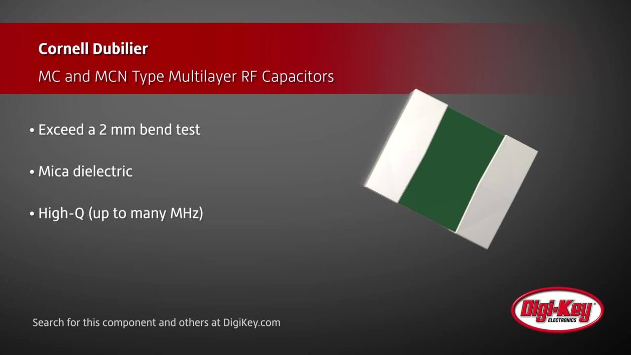
The Cornell Dubilier Electronics’ MC12FD101J-F is a 100 pF, 5%, 500 volt, mica capacitor in a surface mount configuration (Figure 6). It is used in RF applications like MRI, mobile radios, power amplifiers, and oscillators. They are temperature rated to operate over the range of from -55° to 125°C.
 Figure 6: The Cornell Dubilier Electronics MC12FD101J-F is a surface mount mica capacitor intended for RF applications. (Image source: Cornell Dubilier Electronics)
Conclusion
Capacitors are an essential component in electronics design. Over the years a wide range of device types have been developed with various characteristics that make some capacitor technologies particularly suited to specific applications. For designers, acquiring a good working knowledge of the various types, configurations, and specifications is a worthwhile endeavor to ensure the optimal choice is made for a given application.
Disclaimer: The opinions, beliefs, and viewpoints expressed by the various authors and/or forum participants on this website do not necessarily reflect the opinions, beliefs, and viewpoints of DigiKey or official policies of DigiKey.