Control Light ON/OFF Via SMS With SIM900 Module - Visuino Project
2026-04-09 | By Ron Cutts
License: GNU Lesser General Public License Bluetooth / BLE Microcontrollers Wifi Arduino ESP32
In this tutorial, you will learn how to control a light by sending SMS commands using the SIM900 GSM Module and Visuino.
Watch the video!
Special thanks to Finn André Hotvedt for assisting with testing and verifying the correct commands for the SIM900 module.
If you need help with Visuino projects or building a custom prototype using Arduino or other boards, Finn André Hotvedt is a great resource. You can contact him here.
Learn more about Visuino: What is Visuino
What You Will Need
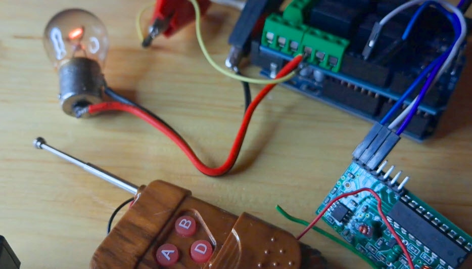
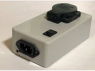
I am using in this tutorial a 5V light bulb module, but you can use anything, such as an LED module, a relay, etc
SIM card (You should disable the PIN request on the SIM card before using it with the GSM shield)
5V power supply with enough amps for the shield
Visuino program: Download Visuino


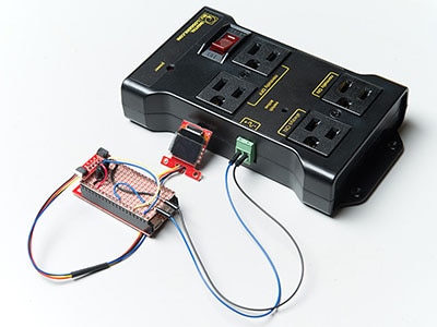
The Circuit
Connect the SIM900 GSM Shield to the Arduino
Connect the LED module pin [VCC] to Arduino (shield) pin [5V]
Connect the LED module pin [GND] to Arduino (shield) pin [GND]
Connect the LED module pin [IN] to Arduino (shield) Digital pin [2]
Connect with the Jumpers on the shield pins D8(RX) & D7(TX) as you see it in the picture
Make sure that the antenna is connected to the shield
Connect the 5V Power Supply to the shield, and set the switch on the shield to the External Power (See the picture)
Once the Power is connected, hold the Power button for 2 seconds
Once the connection with the Network is established, the LED will blink every 3 seconds


Start Visuino, and Select the Arduino UNO Board Type
Start Visuino as shown in the first picture. Click on the "Tools" button on the Arduino component (Picture 1) in Visuino. When the dialog appears, select "Arduino UNO" as shown in Picture 2


In Visuino, Add Components
Add "Software Serial Port" component
Add 2X "Compare Text Value" component
Add 3X "Digital Multi Source" component
Add "Char To Text" component
Add "Start" component
Add "Text Value" component
Add "Toggle(T) Flip-Flop" component


In Visuino Set Components
Double-click on the "TextValue1" and in the Elements window
Drag "Set Value" to the left side and in the properties window set "Value" to AT+CMGD=1,4
Drag another "Set Value" to the left side and in the properties window set "Value" to AT+CNMI=1,2,0,0,0
Close the Elements window
Select "CompareValue1" and in the properties window set "Value" to Light ON and "Ignore Case" to True
Select "CompareValue2" and in the properties window set "Value" to Light OFF and "Ignore Case" to True


In Visuino Connect Components
Connect "Start1" pin [Out] to "MultiSource1" pin [In]
Connect "SoftwareSerial1" pin [RX] to Arduino Digital pin [7]
Connect "SoftwareSerial1" pin [TX] to Arduino Digital pin [8]
Connect "SoftwareSerial1" pin [Out] to "CharToText1" pin [In]
Connect "CharToText1" pin [Out] to "CompareValue1" pin [In]
Connect "CharToText1" pin [Out] to "CompareValue2" pin [In]
Connect "CompareValue1" pin [Out] to "MultiSource2" pin [In]
Connect "CompareValue2" pin [Out] to "MultiSource3" pin [In]
Connect "MultiSource2" pin [0] to "TFlipFlop1" pin [set]
Connect "MultiSource2" pin [1] to "TextValue1" > "Set Value1": pin [In]
Connect "MultiSource3" pin [0] to "TFlipFlop1" pin [Reset]
Connect "MultiSource3" pin [1] to "TextValue1" > "Set Value1": pin [In]
Connect "MultiSource1" pin [0] to "TextValue1" > "Set Value1": pin [In]
Connect "MultiSource1" pin [1] to "TextValue1" > "Set Value2": pin [In]
Connect "TextValue1" pin [Out] to "SoftwareSerial1" pin [In]
Connect "TFlipFlop1" pin [out] to Arduino digital pin [2]
Optional if you want to monitor response from the GSM shield: Connect "SoftwareSerial1" pin [Out] to Arduino Serial pin [In]


Generate, Compile, and Upload the Arduino Code
In Visuino, at the bottom, click on the "Build" Tab, make sure the correct port is selected, then click on the "Compile/Build and Upload" button.

Play
When you power the Shield, wait a bit for the connection with the network to be established. Once the connection is established, the LED on the shield will blink every 3s.
Now you can send SMS from the phone using the text "Light ON" or "Light OFF" and the LED should turn on or off.
Congratulations! You have completed your GSM project with Visuino. Also attached is the Visuino project that I created for this Tutorial. You can download and open it in Visuino: https://www.visuino.eu